> Source: [sk168317](https://support.checkpoint.com/results/sk/sk168317)
# sk168317 - Guidelines for Cellular Cables and Antennas in 1500 Series LTE Products
| Property | Value |
|----------|-------|
| Solution ID | sk168317 |
| Date Created | 2020-07-29 |
| Last Modified | 2023-06-26 |
| Technical Level | General |
| Products | Spark Firewall (Locally Managed) |
| Versions | R81.10.X |
| Platform | 1500 |
## Solution
Introduction
------------
> 1570/1590 and 1570R WLTE products support the use of an embedded cellular modem and two external antennas that are shipped with the appliance.
>
> In some cases, customers may want to use their own antennas and connect them remotely.
>
> This document includes guidelines for the type of cables, antennas, connectors, adapters, and monitoring parameters used to verify the signal's quality for such installations.
>
> Many mobile carriers require a minimum Total Radiated Power (TRP), which requires an efficient antenna. It is the customer's responsibility to ensure that the product outputs sufficient power to meet the TRP minimum but does not exceed the FCC and IC EIRP limits.
Cable Types
-----------
> The following table describes the common cable types, main parameters to consider, and maximal recommended length.
>
> Antenna cable impedance must be 50 ohm. If there is an impedance mismatch, the RF performance will be impacted. Consult with the cable's vendor as required.
>
> |----------------|-------------------------|---------------------------------------|----------------------------------------|------------------------------------------|
> | **Cable Type** | **Cable Diameter (mm)** | **Signal Loss (db) @800MHz 3m (10')** | **Signal Loss (db) @1900MHz 3m (10')** | **Maximal Cable Recommended Length (m)** |
> | RG174U | 2.5 | 3.58 | 6.66 | 3 |
> | RG58U | 5.0 | 1.00 | 2.66 | 10 |
> | LMR195 | 5.0 | 1.12 | 2.54 | 16 |
> | LMR200 | 5.0 | 0.99 | 2.30 | 18 |
> | LMR400 | 10.0 | 0.40 | 1.07 | 100 |
> | 1250 | 12.5 | 0.18 | 0.48 | 200 |
>
>
>
>
>
Connector Types
---------------
> The appliance uses an RP-SMA connector. The connector types listed below are commonly used in installations and require an adapter from the RP-SMA to the desired connector. **Note** : Using an adapter may cause additional signal loss and attenuation.
>
> |----------------------------------------------------------------------------------------------------------------------------------------------------------------------------------------------------------------------------------------------------------------------------------------------------------------------------------|---------------------------------------------------------------------------------------------------|
> | **SMA Connector** SMA stands for Subminiature Version A. This is a minimal connector interface for a coaxial cable with a screw-type coupling mechanism. It has an impedance of 50 Ohm and is designed for use from DC (0 Hz) to 18 GHz. Applications include microwave systems, handheld radios, and mobile telephone antennas. | 
|
> | **F-Type Connector** A mid-size connector designed for common use. It is the most widely used connector for residential wiring and is used with cable television, satellite television, and cable modems. It is commonly used with RG-6/U Cable. | 
|
> | ### **N-Type Connector** A larger connector, designed to be used with thick or commercial cable. | 
|
Antenna Types
-------------
> There are many types of cellular antennas for use with the 1500 Series security appliances. Review the relevant antennas to determine which best meet your installation and site requirements.
>
> **Important** **Compliance Information for North American Users** :
>
> To comply with FCC/IC regulations limiting both maximum RF output power and human exposure to RF radiation, the maximum antenna gain including cable loss **must not exceed** the limits below:
>
> |----------------|----------|-------------------------|--------------------------------|
> | **Technology** | **Band** | **Frequency** **(MHz)** | **Maximum antenna gain (dBi)** |
> | LTE | 2 | 1850-1910 | 6 |
> | LTE | 4 | 1710-1755 | 6 |
> | LTE | 5 | 824-849 | 6 |
> | LTE | 7 | 2500-2570 | 6 |
> | LTE | 12 | 699-716 | 6 |
> | LTE | 13 | 777-787 | 6 |
> | LTE | 25 | 1850-1915 | 6 |
> | LTE | 26 | 814-849 | 6 |
> | 3G UMTS | 2 | 1850-1910 | 6 |
> | 3G UMTS | 4 | 1710-1755 | 6 |
> | 3G UMTS | 5 | 824-849 | 6 |
>
>
>
> In general, the embedded cellular modem may transmit simultaneously with other collocated embedded radio transmitters as WiFi. The output power and antenna gain in a collocated configuration must not exceed the limits below:
>
> |------------|-----------------|------------------|
> | Technology | Frequency (MHz) | EIRP limit (dBm) |
> | WiFi | 2400-2500 | 25 |
> | WiFi | 5150-5850 | 27 |
>
>
>
>
>
>
>
> |------------------------------------------------------------------------------------------------------------------------------------------------------------------------------------------------------------------------------------------------------------------------------------------------------------------------------------------------------------------------------------------------------------------------------------------------------------------------------------------------------------------------------------------------------------------------------------------------------------------------------------------------------|------------------------------------------------------------------------------------------------------|
> | **Omni Antenna** Omni antennas radiate a signal in a 360� donut pattern. They are one of the most commonly used and versatile antennas due to their ability to receive and transmit in any direction. Because their beam-width pattern is not concentrated in a particular direction, they are generally lower in gain than other types of antennas. Typical gain: 0 - 9dBi Click [here](https://www.southwestantennas.com/omni-antennas/cellular-band-omni-antennas/1001-146) for an example. | **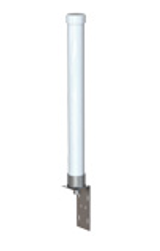**
|
> | **Yagi Antenna** A Yagi antenna is ideal for point to point and line of site applications. Made from stainless steel or aluminum, they consist of a long boom with elements strategically placed at intervals. The greater the number of elements, the higher the gain. Longer elements support lower frequencies; shorter elements support higher frequencies. The Yagi antenna is usually high in gain and good for long distance communications. Typical uses include pole mounts on a building. Typical gain: 10 - 16 dBi Click [here](https://www.wilsonamplifiers.com/wilson-yagi-directional-antenna-wide-band-50ohm-314411/) for an example. | ****
|
> | **Parabolic / Grid Antenna** Parabolic antennas are ideal for long range communications, providing a greatly focused directional signal. The dish plate acts as a reflector to highly concentrate the signal in a particular direction. Parabolic antennas are usually very high gain. Typical gain: 15 - 26 dBi Click [here](https://www.signalbooster.com/products/directional-parabolic-grid-antenna-for-cell-phone-wifi) for an example. | **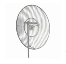**
|
> | **Panorama Antenna** Panorama antennas are usually a combination antenna of cellular, WiFi, and GPS. They offer a robust solution in vehicle applications and combine several technologies into a single antenna design. Typical gain: 15 - 26 dBi Click[here](http://www.panorama-antennas.com/site/index.php?route=product/product&product_id=288) for an example. |  |
Factors that impact the cellular signal strength and monitoring parameters
--------------------------------------------------------------------------
Factors that influence signal strength and quality include:
> * Proximity to the cellular cell and load
> * Interfering signals
> * Weather conditions
> * Physical barriers (such as buildings, mountains, etc.)
>
> The parameters below define system signal strength and can be monitored by the software command line (show cellular-modem-status). For more information, refer to the [1500 Appliance Series Administration Guide (Locally Managed)](https://sc1.checkpoint.com/documents/SMB_R80.20.10/AdminGuides/Locally_Managed/EN/Content/Topics/Check-Point-1500-Appliance-Series-Overview.htm).
>
> * Signal Strength (RSSI)
> * LTE Signal Strength (RSRP)
> * LTE Signal Quality (RSRQ)
> * LTE Signal Interference (SNR)
> * 3G Signal Quality (ECI0)
>
> **Signal Strength (RSSI)** - Received Signal Strength Indicator
>
> This is the average received signal power measured in the air interface channel. It indicates if there is a strong signal available for the 1500 Security Gateway to connect to.
>
> |---------------------|-----------------|
> | RSSI | Signal Strength |
> | \> -78 dBm | Good |
> | -78 dBm to -93 dBm | Fair |
> | -94 dBm to -102 dBm | Poor |
> | \< -103 dBm | Inadeqate |
>
>
>
>
>
> **LTE Signal Strength (RSRP)** - Reference Signal Received Power
>
> This is the average signal power of all cell-specific reference signals within the LTE channel. It indicates whether the 1500 Security Gateway has a strong connection to the wireless network. The value varies depending on the network characteristics and the Gateway.
>
> |-----------------------|---------------------|
> | **RSRP** | **Signal Strength** |
> | \> -105 dBm | Good |
> | -105 dBm to -115 dBm | Fair |
> | -116 dBm to -1000 dBm | Poor |
> | \< -1000 dBm | Inadequate |
>
>
>
>
>
> **LTE Signal Quality (RSRQ)** - Reference Signal Received Quality
>
> The RSRQ indicates the quality of the 1500 Security Gateway's connection to the wireless network. The value varies depending on the network characteristics and the Gateway.
>
> |-------------------|---------------------|
> | **RSRQ** | **Signal Strength** |
> | \> -9 dBm | Good |
> | -9 dBm to -12 dBm | Fair |
> | \< -12 dBm | Poor |
>
>
>
>
>
> **LTE Signal Interference (SNR)** - Signal to Noise and interference Ratio
>
> Higher values indicate that signal power is much greater than the noise and interference.
>
> |---------|----------------|
> | **SNR** | **Throughput** |
> | \> 10 | Excellent |
> | 6 - 10 | Good |
> | 0 - 5 | Fair |
> | \< 0 | Poor |
>
>
>
>
>
> **3G Signal Quality (ECI0)**
>
> This indicates the signal quality with a ratio of the average signal energy to co-channel interference in dB.
>
> |------------|--------------------|
> | **ECI0** | **Signal Quality** |
> | 0 to -6 | Good |
> | -7 to -10 | Fair |
> | -11 to -20 | Poor |
>
>
>
>
>
> If you experience any connection problems:
>
> * Make sure the values of the parameters above are within the "good" range.
> * Make sure the antennas are properly plugged in and installed.
> * Contact the service provider.
> * Try another service provider as a reference.
> * Move the appliance or antenna to another location.
> * Try another type of antenna.
---
# Agent Instructions
This content is from the Check Point Support Center (https://support.checkpoint.com), the official knowledge base for Check Point cybersecurity products.
## Navigating This Knowledge Base
- **Complete index**: [llms.txt](https://support.checkpoint.com/llms.txt)
- **All SK articles**: [SecureKnowledge Sitemap](https://support.checkpoint.com/sitemaps/secureknowledge-sitemap-index.xml)
- **SK article URL pattern**: `https://support.checkpoint.com/results/sk/{skId}`
- **Markdown responses**: AI bot User-Agents automatically receive `text/markdown` content